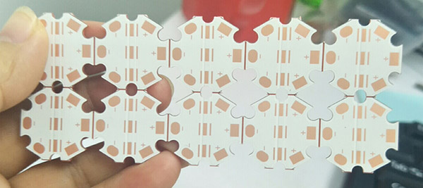
As a carrier of various components and a hub of circuits signal transmission, PCB has become the most important and critical part of electronic information products. Its quality and reliability determine the quality and reliability of the equipment. However, due to the cost and technical reasons, the PCB has a large number of failures in the process of production and application.
For this kind of failure problem, we need some common failure analysis techniques to ensure the quality and reliability of PCB in manufacturing. This passage summarizes ten failure techniques for reference.
1. Appearance Inspection
Appearance inspection is that visual inspection or use of simple instruments to inspect the appearance of PCB by tools of stereoscopic microscope, metalloscope and even magnifying glass, and to look for lost parts and related physical evidence. The main function is failure localization and preliminary judgement of PCB failure mode. The appearance inspection mainly checks the pollution, corrosion, the position of the detonation board, the wiring of the circuit and the regularly of failure, whether the batch or individual is always concentrated in a certain area and so on. In addition, a lot of PCB failure is found after assemble PCBA, whether the assembly process and the influence of process materials lead to the failure, which is needed to carefully check the failure characteristics of the area.
2. X-Ray Fluoroscope
For those parts, that can not be inspected through the appearance and the hole internal and other internal defects of PCB, we have to use X-Ray fluoroscope to check. X-ray fluoroscope is to use different material thickness or different material density to the X-ray absorption or though the different principle of the rate of imaging. This technique is used to check the defects inside the PCBA solder joints, the internal defects of the holes, and the positioning of the defect solder joints of BGA or CSP devices. The resolution of the current industrial X-ray equipment can achieve a micron, and is from 2D to 3D imaging equipment, even five dimensions (5D) equipment used for inspection of packaging, but this kind of 5D X-ray system is very valuable, rarely has practical application in industry.
3. Slice Analysis
Slice Analysis is the process of the obtaining the cross section structure of PCB by means of sampling, inlaying, slicing, polishing, corrosion and observation. Through slice analysis, we can get rich information about the micro-structure of PCB (through hole, coating etc.), which can provide a good basis for the next step of quality improvement. But the method is destructive. Once sliced, the sample must be destroyed. Meanwhile, this method requires a high level of legal requirements, and it takes a long time to make a sample, which needs a skilled technician to complete. The detail slice operation process is required to refer the process of IPC standard IPC-TM-650 2.1.1 and IPC-MS-810.
4. Scanning Acoustic Microscope (SAM)
Currently, the C mode ultrasonic scanning microscope is mainly used for electronic encapsulation or assembly analysis. It took advantage of high frequency ultrasound imaging which materials is changed by the resulting amplitude and phase and polarity under the discontinuous interface reflection. The scanning method is to scan the X-Y plane along the Z axis. Therefore, the scanning acoustic microscope can be used to detect components, materials, internal defects of PCB and PCBA, including cracks, layers, inclusion, and holes, etc.. If the frequency width of the scan acoustics is sufficient, the internal defects of solder joints can be detected directly.
The typical scanning acoustic image is a alert color of red indicating the presence of a defect. Because the large number of plastic packaging components are used in SMT process. A large amount of wet reflux is produced, which the moisture-absorbent plastic sealing device will appear in the internal or substrate layer cracking phenomenon when the higher lead-free process temperature is returned. In the high temperature of lead-free process, ordinary PCB will often appear. At this point, the scanning acoustic microscope highlights its special advantages in multilayer high density PCB nondestructive testing. However, the obvious detonation plate can be detected by visual appearance alone.
5. Microscopic Infrared Analysis
Microscopic infrared analysis is the method of combining infrared spectra with microscope. It uses different materials (mainly is organic compounds) to absorb different infrared spectra, analyzes the chemical composition of the materials, combines with microscopy which makes visible light with infrared light. As long as you are in the visible field, you can look for trace organic pollutants.
If there is no microscopy, usually the infrared spectrum can only analyze a sample with a large sample size. In the electronic process, a lot of situation is that trace pollution can lead the poor solder-ability of pads or leads of PCB. As you can image, it is difficult to solve the process problem without the infrared spectrum of microscope. The main purpose of the micro-infrared analysis is to analyze the organic pollutants on the surface of weld or solder joints, analyze the cause of corrosion or weld-ability.
6. Scanning Electron Microscope (SEM)
Scanning Electron Microscope (SEM) is one of the most useful large electron microscopic imaging system for failure analysis. Its working principle is to use cathode emission electron beam via anodic acceleration. A beam of electrons with a diameter of tens to thousands (A) is formed by the focus of the magnetic lens. Under the effect of scanning deflection coil, the electron beam in a certain time and space order in the sample surface point by point scanning movement, the beam of high energy electron beam bombardment to the sample surface will inspire a variety of information, through collecting amplification can get various corresponding graphics from the screen.
The excited secondary electrons are produced within 5 ~ 10nm of the sample surface. Therefore, the secondary electron can better reflect the surface morphology of the sample, which it is most commonly used to observe the morphology. The excited back-scattered electrons are generated within 100 ~ 1000nm of the sample surface. The back-scattered electrons of different characteristics are emitted as the atomic number of the material is different. Therefore, the back-scattered electron image has the capability of distinguishing feature and atomic number, And also the back-scattered electron image can reflect the distribution of chemical elements. The current scanning electron microscope is very powerful, and any fine structure or surface features can be magnified to hundreds of thousands of times for observation and analysis.
On PCB or solder joint failure analysis, SEM is used to make a failure mechanism analysis, specifically used to observe the morphology structure of the welding plate surface inter-metallic compound, solder joint micro-structure, measurement, analysis of weld-ability coating as well as the analysis of the tin whisker measurements. Different from optical microscope, scanning electron microscopy (sem) is a electronic like, so only black and white and dichromatic, and scanning electron microscopy (sem) conductive sample requirements, part of nonconductor and semiconductor need to spray gold or carbon, gathered in the surface charge will influence the observation of the sample. In addition, the scanning electron microscope image depth is much larger than the optical microscope, which is an important analysis method for the metallographic structure, micro-fracture and tin whisker.
7. Energy Analysis of X Ray
The scanning electron microscopy (sem) mentioned above is usually equipped with an X-ray energy spectrometer. When the high-energy electron beam hit the surface, the surface material of the inner electrons in the atoms are bombarded escape, outer electrons to low energy level transition will inspire characteristic X ray, atomic energy level difference of different elements from different characteristic X ray is different, therefore, can send sample of the characteristics of X-ray as chemical composition analysis.
At the same time, according to the detection signal for the characteristics of X-ray wavelength or equipment were called spectral characteristics and the corresponding energy dispersive spectrometer (hereinafter referred to as spectrometer, WDS) and energy dispersive spectrometer (hereinafter referred to as spectrometer, EDS), the resolution of the spectrometer is higher than spectrometer, spectrometer analysis speed is faster than spectrometer.Because the energy spectrometer is fast and low cost, the general scanning electron microscope is equipped with energy spectrometer.
As the scanning mode of electron beam is different, the energy spectrometer can carry out the surface analysis, line analysis and surface analysis, and can obtain the information of different distribution of elements.Point analysis gets all of the elements;The line analysis performs an elemental analysis of a specified line at a time, and the line distribution of all the elements is scanned multiple times.Analysis of all elements in a given surface, the measured element content is the average of the measured surface area.
In the analysis of PCB, the energy spectrometer is mainly used to analyze the composition of the surface of the welding disc, and the element analysis of the surface contaminants of the welded disk and lead foot.The accuracy of the quantitative analysis of the spectrometer is limited, less than 0.The 1% content is not easily detected.The combination of energy spectrum and SEM can obtain the information of surface topography and composition at the same time, which is why they are widely used.
8. XPS Analysis
Samples by X ray irradiation, the surface of the inner shell electrons of the atom will escape from the bondage of the nucleus and solid surface forming, measuring its kinetic energy the Ex, the inner shell electrons of the atom can be obtained the binding energy of Eb, Eb varied from different elements and different electron shell, it is the "fingerprints" of the atom identification parameters, formation of spectral line is XPS, which can be used for qualitative and quantitative analysis of superficial surface (several nano-level) elements in the sample surface.
In addition, the chemical valence state of the element can be obtained according to the chemical displacement of the binding energy. It can give the surface layer valence state and the surrounding element bond and so on information. The incident beam is an X-ray photon beam. Therefore, the insulation sample analysis can be carried out, and the analysis of the rapid multi-element analysis of the samples without damage is analyzed. The longitudinal distribution of the elements can be analyzed in the case of argon ion dissection. And the sensitivity is higher than the EDS. The analysis of XPS in PCB is mainly used for the analysis of the quality of the coating, the analysis of the pollutants and the degree of oxidation, so as to determine the underlying causes of weld-ability.
9. Differential Scanning Calorimetry of Thermal Analysis
A method of measuring the power difference between material and reference material in relation to temperature (or time) under program control temperature. DSC under the sample and reference container heating wire is equipped with two sets of compensation, when the sample due to the thermal effect in the process of heating and temperature difference between reference objects Δ T, through differential thermal amplifying circuit and differential amplifier heat compensation, make the change into the compensation current of electric wire. Δ T disappear and make the heat balance on both sides, temperature difference, and record the sample and reference substance under the difference between the two electric heating compensation thermal power relations, along with the change of temperature (or time), according to the relationship between the change to study physical chemical and thermodynamic properties of materials. DSC is used widely, but in the analysis of PCB is mainly used for measuring all kinds of high polymer materials used in the PCB, glassy state transformation temperature of curing degree, these two parameters determine the reliability of PCB in the subsequent process.
10. Thermal Mechanical Analyzer (TMA)
Thermal Mechanical Analyzer (TMA) is to measure the deformation properties of solids, liquids and gels under thermal or mechanical force. The common methods of loading are compression, needle insertion, stretching, bending, etc.. The test probe is supported by a cantilever beam and a spiral spring attached to it, through the motor applying load to the sample. When the specimen deformation occurs, differential transformer to detect the change, and together with the data processing, such as temperature, stress and strain after the material can be obtained under the negligible load deformation relations with temperature (or time).
According to the relationship between deformation and temperature (or time), the physical, chemical and thermodynamic properties of the materials can be researched and analyzed. The wide application of TMA, the analysis of PCB is mainly used for the two key parameters of PCB, which measures the linear expansion coefficient and the glass transition temperature. The PCB of the base material with too large expansion coefficient often leads to the fracture failure of the metallized hole after welding assembly.
Because of the development trend of PCB high density and the environmental protection requirement of lead-free and halogen free, more and more PCB has the problems of wetting,blasting, layering, CAF and so on. This paper introduces the application of these analytical techniques in the practical cases. The failure mechanism and reason for obtaining of PCB will be beneficial to the quality control of PCB in the future, so as to avoid the recurrence of similar problems.